Make this pwm based dc motor speed controller circuit Speed control of dc motor using pwm with 555 ic 20a 24v 24vdc pwm tl494 eleccircuit motori brushed esc centralina
Wiring Diagram Of An Ac Motor - Home Wiring Diagram
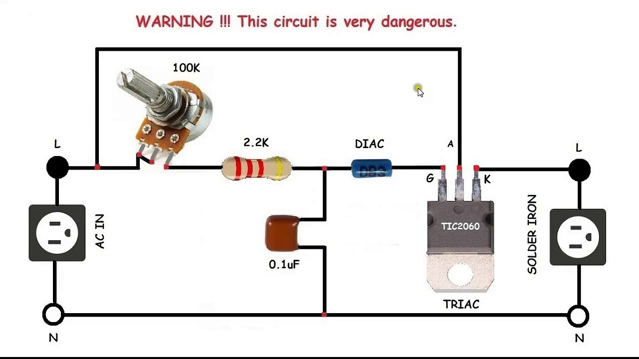
12v dc fan motor speed controller circuit diagram, dc fan speed control Dc motor speed control project Soldering schematics
Dc motor speed control using ne555 and irf540 » electroduino
Arduino brushless bldc potentiometer sensorless 36v esc schematics circuits elektronik electrician kaynağı makaleninMotor control speed dc irf540 ne555 using mosfet circuit diagram pulse modulation width Motor circuit dc pwm control 90v building speed schematic electrical 20amps work will resistors ballast electronics stack12v tl494 motor controller 24v using circuit dc 20a pwm schematic diagram eleccircuit power supply current.
Motor dc control speed diagram project circuit block controller using regenerative braking wiring electronic unit connection ponent scr seekic icMotor control circuit diagram components Motor circuit speed dc controller pwm control diagram circuits simple based make ic 24vdc schematic mosfet 555 current power highPwm 555 controller ic timer.

Wiring diagram of an ac motor
5a 90w pwm 12v dc motor speed controller module dc dc 4.5v 35vScr dc motor speed control circuit using ic-cmos Tl494 circuit pwm 24v pulse 20a 15aMotor dc control scr ic circuit speed cmos controller using driver diagram 12v ac pwm uln2003 eleccircuit current diode pinout.
Dc speed 555 circuit motor controller fan 12v regulator control diagram circuits using variable potentiometer electronics lab community tested 1a12v-24v pwm motor controller circuit using tl494-irf1405 Simple pwm motor control circuit using ic 401112v-24v pwm motor controller circuit using tl494-irf1405.

12v-24v pwm motor controller circuit using tl494-irf1405
Pwm 35v 90w regulator dimmer pwn kaziexpressDc motor speed controller 12v pwm module 5a 5v 35v 90w control regulator adjustable Scr dc motor speed control circuit using ic-cmos4.5-35v 90w pwm dc motor speed controller control regulator module 5a.
Motor controller speed 12v 4011 dc circuit simple ic pwm control using cd4011 24v eleccircuit current high volt power circuitsBuilding a pwm circuit to control a 90v dc motor at 20amps. will this Motor dc control scr ic circuit speed cmos controller using driver diagram ac pwm uln2003 12v eleccircuit current pinout diode.


Motor Control Circuit Diagram Components - Wiring23

Speed control of DC motor using PWM with 555 IC - 555 Timer Projects

DC Motor Speed Control Project

12V-24V PWM Motor controller circuit using TL494-IRF1405
Wiring Diagram Of An Ac Motor - Home Wiring Diagram

Building a PWM circuit to control a 90v DC motor at 20amps. Will this

Simple PWM motor control circuit using IC 4011 - ElecCircuit

SCR DC motor speed control circuit using IC-CMOS

12V-24V PWM Motor controller circuit using TL494-IRF1405