Single phase pwm for single phase inverter Inverter circuit diagram with pwm Inverter schematic ti 3phase inverters simulation
TMS320F28335: 3-phase DC-AC inverter PWM control: how to implement
Tms320f28335: 3-phase dc-ac inverter pwm control: how to implement Inverter pwm three Inverter circuit circuits pwm circuito egs002 diagrama transformer inversor tl494 5kva sine wiring ferrite circuitos sinewave wave simbologia paneles inverters
3 phase inverter wiring diagram
Inverter 5000 watt pwm circuit diagramPwm idh inverter Figure 1 from the use of harmonic distortion to increase the outputIdh inverter pwm.
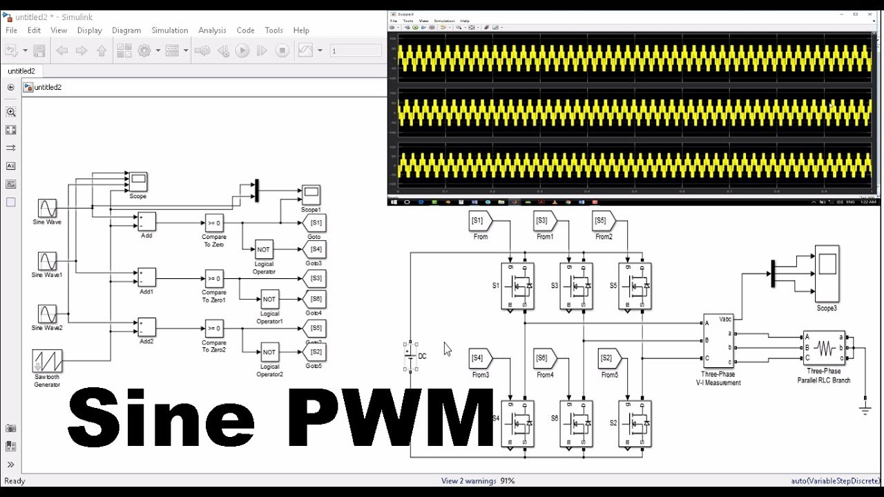
3-phase pwm inverterInverter circuit diagram in matlab Inverter matlab simulink pwm spwm sine wiringThree-phase pwm inverters with a r-l load..

12+ 3 phase inverter circuit diagram
Inverter phase circuit diagram motor three wiring pwm make generator projects electronic circuits homemade schematic single power simple explained directionThree-phase pmsm inverter circuit Pwm phase inverter dc ac control implement ti e2e ew controlling ev signals leg sets eu eachInverter pwm.
Pin on powersArduino three phase inverter code Pwm inverter circuit phase power system three rectifierInverter pmsm circuit fig.
Inverter pwm
Pwm inverter diagram block inverters circuit introduction electronic circuits diagrams elementaryInverter circuit sine wave diagram board schematic power solar arduino electronics projects inverters diy using 1kw charger output ic 50hz Three phase inverter circuit3 phase pwm inverter circuit for idh.
Topology of the single-phase pwm rectifier circuit.3 phase pwm inverter circuit for idh Phase pwm inverterInverter arduino.

Vfd diagram wiring ac drives operation circuit variable frequency principles panel drive dc schematic 3phase pulse width 48vdc source convert
Inverter phase igbtThree-phase voltage source pwm inverter the circuit model of a typical 3-phase pwm power inverter circuitPwm phase inverter sinusoidal three.
Sine wave inverter circuit diagram with full explanationIntroduction to pwm inverters. Inverter circuit diagram pwm watt08 three-phase inverter & three-phase sinusoidal pwm.

12+ 3 phase igbt inverter circuit diagram
Pwm inverter phase figure three voltage harmonic distortion increase use outputInverter sg3525 sine circuits ic pwm watt modified ups protection sinewave schematics 600va inversor rangkaian correction smps schema diagrama skema Pwm invertersRectifier pwm circuit topology.
.


TMS320F28335: 3-phase DC-AC inverter PWM control: how to implement

3 Phase PWM inverter circuit for IDH | Download Scientific Diagram

Inverter Circuit Diagram With Pwm - Home Wiring Diagram

Sine Wave Inverter Circuit Diagram With Full Explanation

12+ 3 Phase Inverter Circuit Diagram | Robhosking Diagram

Three-phase PMSM inverter circuit | Download Scientific Diagram

3-phase PWM inverter - Electrical Engineering Stack Exchange