Adder subtractor binary circuit bit diagram coa logic block javatpoint mode Solved build the adder-subtractor circuit from page 18 from Adder subtractor logic
4 bit full adder/subtractor circuit - YouTube
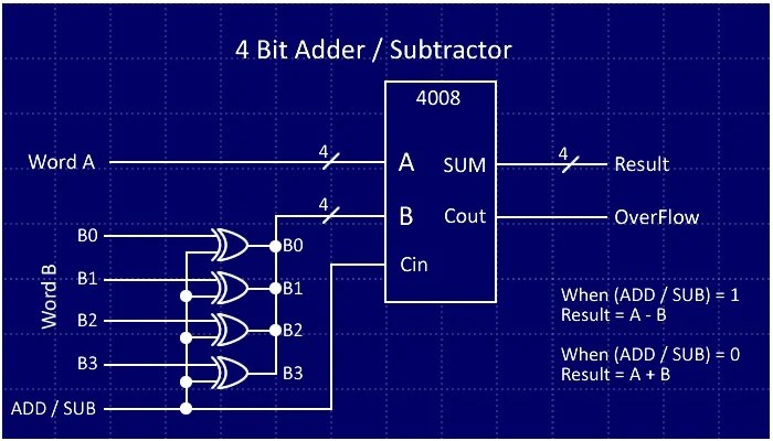
Let's learn computing: 4 bit adder/subtractor circuit Bit adder subtractor circuit carry ripple logic Lesson 13 binary adder subtractor in vhdl
4-bit serial adder/subtractor with parallel load – altynbek isabekov
4-bit serial adder/subtractor with parallel load – altynbek isabekovLet's learn computing: 4 bit adder/subtractor circuit Subtractor adderBinary adder/subtractor.
Adder serial subtractor module schematicsTwos complement Solved the 4 bit adder/subtractor circuit implemented withAdder serial subtractor verilog flop flip registers vhdl module schematics simplified.
10+ adder circuit diagram
4-bit serial adder/subtractor with parallel load – altynbek isabekovAdder circuit diagram schematic bit works figure How to build your own discrete 4-bit aluAdder subtractor bit circuit binary 7483 ic signed input explain solved dd.
Digital logic design: binary parallel adder/subtractorAdder bit subtractor circuit values consider following input mode has help steps solve thank displayed figure questions solved Adder subtractor binary vhdlAdder subtractor bit circuit add sub overflow questions complement logic detection carry addition designing control zero line digital find.

Logic adder subtractor parallel binary circuit bit diagram control signal mode digital determines which has
Full-adder circuit, the schematic diagram and how it works – deeptronicBit alu adder build subtractor logic arithmetic unit project simple cpu complete discrete allaboutcircuits own Solved: consider the 4-bit adder/subtractor circuit displa...Adder subtractor complement subtraction minus carryout overflow twos.
4 bit full adder/subtractor circuitAdder bit subtractor circuit ripple carry diagram logic using project build only digital computing learn let its single indie electronics Adder serial bit subtractor parallel load number xilinx two negated ise schematics drawnAdder subtractor bit make carry ripple verilog circuit binary diagram using 4bit want geeksforgeeks output hdl has source.

Adder subtractor logic add sub combinational circuits bit binary using subtraction tutorial adders electronics
Digital logic .
.


4 bit full adder/subtractor circuit - YouTube

Solved The 4 bit adder/subtractor circuit implemented with | Chegg.com

Let's Learn Computing: 4 bit Adder/Subtractor Circuit

10+ Adder Circuit Diagram | Robhosking Diagram

digital logic - Designing a 4-bit adder-subtractor circuit - Electrical

Binary Adder/Subtractor | Combinational logic circuits | Electronics

Solved: Consider The 4-bit Adder/subtractor Circuit Displa... | Chegg.com

COA | Binary Adder-Subtractor - javatpoint