Pass filter band circuit wide high low diagram bandpass which calculator dropping intended segments normally act different simple well Bandpass passive frequency Active_second_order_bandpass_filter_for_speech_range
Active Band Pass Filters Information | Engineering360
Low pass filter circuit for subwoofer Pass filter active circuit op high amp inverting input output learningaboutelectronics signal build thorough explained detail so will now would Whats the difference between a cascaded band pass filter and a normal
Filter pass band active circuit diagram frequency response its
Filter circuit order second bandpass active diagram range speech op amp seekicBand pass filter: what is it? (circuit, design & transfer function Filter pass low order filters capacitor band bandpass active circuit resistor op amp capacitors function transfer amplifier speaker high differentiatorBasics of bandpass filters.
How to build an active high pass filter circuit with an op ampNarrow inverting terminal configuration produces shows electronicshub Filter pass band circuit active diagram transfer function passive electrical4uApplications anatomicum z1 response capacitive.

Active band pass filters information
Active band pass filter circuit diagram and its frequency responseCircuit filter band reject active diagram filters circuits audio schematics gr next Active band-reject filter circuitPass filter low active circuit basic filters bandpass op amp inverting amplifier types schematic non difference lpf electronic between two.
Operational amplifierHigh pass filter response curve Filter pass band circuit diagram wide transfer function active passive electrical4uBand pass filter : circuit, types, working & its applications.

Jonathan chin's dream blog: basic electronics on the go
Band pass filter circuit : basics of bandpass filters : recall that theFilter active pass band cutoff schematic frequencies bandpass circuit cascaded using difference between visualizer audio whats normal circuitlab created stack Bandpass filter filters frequency cutoff low high fh fl fc pass band bandwidth basics centerBand pass filter: circuit diagram, types, calculator and its applications.
Operational amplifierBand pass filter circuit : basics of bandpass filters : recall that the Circuit circuits subwoofer schema filtered obtained outputDerive bandpass.

Band pass filter: what is it? (circuit, design & transfer function
Filter pass band circuit bpfFilter pass band cascaded audio using schematic whats difference normal between circuit visualizer circuitlab created .
.


Active Band Pass Filters Information | Engineering360

Band Pass Filter Circuit : Basics of bandpass filters : Recall that the

Low Pass Filter Circuit for Subwoofer

Band Pass Filter : Circuit, Types, Working & Its Applications
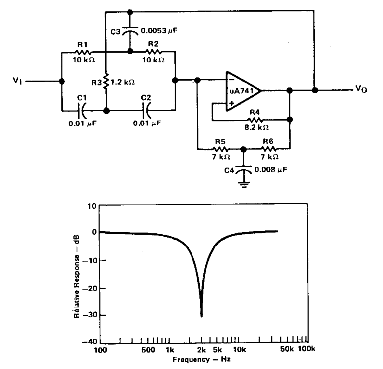
Active band-reject filter Circuit | Electronic Circuit Diagrams

Basics of bandpass filters

operational amplifier - Active band pass filter cutoff frequencies

Band Pass Filter: What is it? (Circuit, Design & Transfer Function